
Solid Edge - How to reattach a bolt circle and its dependant dimensions
How to reattach a bolt circle and its dependant dimensions
(Draft environment)
Introduction
Draft annotations and dimensions rely heavily on their support geometry. Since it is possible with Solid Edge to attach dimensions to center marks, center lines and bolt circles; you must know how to reattach those elements when the support geometry is replaced by another one.
Workflow
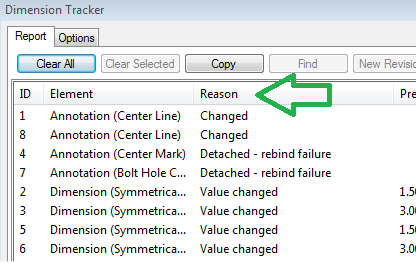
So, as usual, you modified your 3D model and the draft file needs to be updated. After updating the view, a dialog called the ‘dimension tracker’ automatically opens (default setting).
First, you can classify the changes by clicking on the ‘reason’ column header. The changes and auto-reattachments can be validated and cleared (‘Clear Selected’ button) and you can then focus on the detached elements.
The bolt circle example
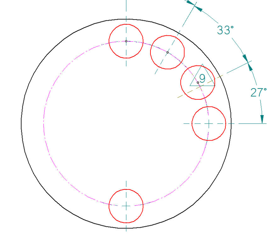
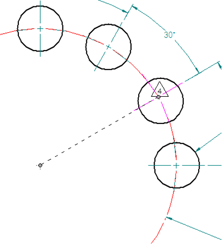
The first thing you need to do is select the bolt circle itself (not the dependant center marks). It should highlight, along with some holes, as shown in the image below and the command bar should also appear.

The two holes shown in red are still used as a reference (Note: in the above example, the bolt circle was created using the 3 points technique and one hole reference was lost).
With the bolt circle itself still selected, if all grey handles have a red hole attached but one of the tracked change (select label to see what gets highlighted) is referencing the bolt circle, skip the next page.
On the other hand, if one of the gray handles doesn’t have a red hole attached to it, you need to reattach that grey handle to another hole.The next page explains how to do this.
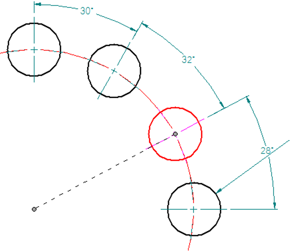
By left-clicking on that grey handle and dragging it on top of a new hole, you can “fix” the bolt circle. You can see (on the image below) how all the holes on the bolt circle are now shown in red when it is selected and one of the change label is gone.
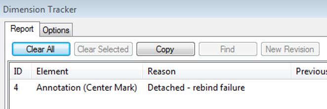
If the dimension tracker is displayed/refreshed, the corresponding change will have been cleared from the list.
Select the bolt circle that indicates a change and drag one outer grey handle on its reference hole while holding the ALT key. If this operation doesn’t repair the “sick” bolt circle, try the same method on another outer grey handle.
As a second step, it is also necessary to reattach the center mark itself. Start by selecting the detached center mark as shown in the image below.
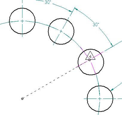
You can see that both the hole and the bolt circle do not highlight (it is different from center marks that are correctly attached).Select the grey dot at the center of the bolt circle and drag it on the bolt circle itself (avoid other center marks and other key points). Selecting the detached center mark should now give you this result (bolt circle shown in red).
The second step is to reattach the centermark itself to the hole. Simply drag it (left click on gray dot at center) on top of the circle with no centermark.
Conclusion
What is important here is that we did not have to delete and recreate any object. We updated our drawing by simply reattaching the handles to the appropriate references.
February 12, 2024